
StruBIM Anchors ACI 318

Checking of anchors used in concrete elements, in accordance with ACI (ACI 318-11 Appendix D or ACI 318-14 Article 17).
StruBIM Anchors ACI 318 is integrated in the Open BIM workflow via the BIMserver.center platform.
Description
StruBIM Anchors ACI 318 is a program to check anchors used in concrete elements based on the ACI code (ACI 318-11 Appendix D or ACI 318-14 Article 17). Checks cast-in-place and post-installed anchors.
Types of anchors
Below are the types of anchors that StruBIM Anchors ACI 318 can check:
- Cast-in-place anchors
- Head bolt
- L-bolt
- J-bolt
- Welded headed stud
- Post-installed anchors
- Adhesive anchors
- Undercut anchors
- Torque-controlled expansion anchors with sleeve and stud
- Displacement-controlled expansion anchors
Data introduction
When a new project is begun, the program allows users to:
- Connect to an existing BIM model located on the BIMserver.center platform
- Create a new project on the BIMserver.center platform
- Begin a project that is not linked to a BIM model
Once the project has been created, the on-screen program interface to introduce data and obtain results is organised as follows:

- Header
Operates the same way as most CYPE programs. It contains tools to manage files (program logo), save the project and create check reports of the selected connections. - Toolbar (below the header)
- To the left
It includes the tools to select the code and analyse the project. - To the right
If the project is linked to a BIM model, the tool to export the data that has been analysed to the BIM model is shown as well as the user that is connected to the BIMserver.center platform.
- To the left
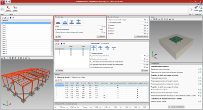
- Left column
Contains a list with the anchor groups that have been introduced by the user (e.g. a series of anchorage plates). If the project that has been created is linked to a BIM model that contains a structural model, a 3D view of the BIM model will appear below the list. - Centre column
Here, users introduce all the data of the connection that is selected in the list of the left column. The following are defined for each group:
- Anchorage plate
The anchorage plate can be created and edited. Its geometry can be any users wish as long as it consists of a polygon, for which users must introduce its points. As far as the plate is concerned, any geometry composed of a polygonal can be introduced, for which, users introduce its points. For design purposes, the plate is considered rigid. It can be level with the concrete, on a mortar filling or suspended from the anchors. In this last case the program distinguishes whether the anchors have a washer and base nut in contact with the concrete or not. Furthermore, the metal section can also be created. It can be an I-section, circular hollow section or rectangular hollow section. - Concrete element
Users can edit its thickness, reinforcement, their minimum cover and distance from each edge of the concrete element to the geometric centre of the section. - Anchors
This panel contains information regarding the anchors: their position with respect to the geometric centre of the section, type of anchor and its geometric properties. - Forces
Here, users introduce either the forces the section transmits to the plate (axial, shear and bending moments in both directions and torsional moment) or the forces directly on each anchor (axial and shear forces in both directions). It is possible to introduce several load combinations.
When the forces the section transmits to the plate are introduced, the forces are those of one-dimensional structural elements: axial, shear and bending moments in both directions and torque.
In the case of plates level with the concrete element or on a layer of mortar, the program performs an iterative calculation, due to the non-linear behaviour of the materials, until the integration of the stresses in the section, given a deformation plane, coincides with the forces imposed by the metallic section. The behaviour of the materials is as follows:
- Anchors
Stress diagram - linear tensile deformation, with a modulus of elasticity of 210 GPa and null in compression (it is assumed they provide no compression resistance). - Concrete and mortar
Stress diagram - deformation with constant compression (AISC Steel Design Guide 1) with a value of 0.85fc (ACI 318-14 22.8.3.2) and null in tension.
- Anchors
When the plate is suspended from the anchors, the concrete does not contribute and the anchors behave linearly in tension and compression.
If the forces are introduced for each anchor, the forces are: axial and shear in both directions. - Anchorage plate
- 3D layout
Allows users to edit the position of the plate - anchor assembly in the context of the project. - Right column
Shows a list of the checks that have been carried out on the selected anchor group. More information on the results provided by the program can be found in the “Results” section.
Checks performed
StruBIM Anchors ACI 318 carries out the following checks:
- Tensile steel capacity
- Tensile breakout capacity
- Tensile pull-out capacity
- Side face blowout capacity of the concrete in tension
- Bond strength of anchor in tension
- Steel shear capacity
- Shear breakout capacity
- Shear pryout capacity
Results
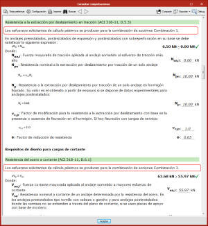
On the right side of the screen, StruBIM Anchors ACI 318 shows the results obtained for the anchor that is selected in the column on the left side.
The program displays a list of the checks that are carried out, which are grouped by type. Each check includes a green or red checkmark to indicate whether the requirement is met, and an icon that opens a dialogue box indicating the details of the check. The data that appears in the dialogue box can be printed out directly or exported to a file in pdf, docx, text, html or rtf format.
As for each check, it is possible to obtain (on-screen, printer or file) the complete list of all the checks carried out for each anchor ("Consult checks" button, located at the bottom of the results column).
During the analysis, the program evaluates all the load combinations that have been entered by users. The reports only provide result details on the worst-case load combination for each check.
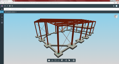
Open BIM workflow
This application is integrated into the Open BIM workflow via the BIMserver.center platform. The program currently has the following exchange of information with the linked BIM model:
- Imports
- The 3D model of the BIM project
If there is a structural model in the linked BIM project, “StruBIM Anchors ACI 318” displays the 3D view of all the models that are imported during the connection with the project.
- The 3D model of the BIM project
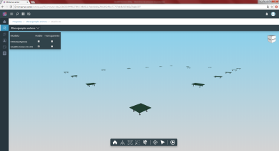
- Exports
- Check report
StruBIM Anchors ACI 318 provides the linked BIM project with the list of the checks of all the anchor groups of the project. - View of the plate and anchors in the context of the project
The 3D view of the plate and anchors is exported to the BIM project via a GLTF file contained in the IFC file that is generated by the program.
- Check report
More information
Download, resources and available languages, license requirements...
Tel. USA (+1) 202 569 8902 // UK (+44) 20 3608 1448 // Spain (+34) 965 922 550 - Fax (+34) 965 124 950